Olympus 올림프스 위상차 렌즈 PLL 4개 세트 입니다.
100/200/400/1000 배율용 이고 각 모델번호와 초점거리는 아래와 같습니다.
 PLL100 1.30 (HiPLL) - working distance : 0.20mm PLL40 0.65 0.17 - working distance : 0.38mm PLL20 0.40 0.17 - working distance : 4.3mm PLL10 0.25 - working distance : 8mm PLL 렌즈는 Phase Contrast Positive Low Low로 콘트라스트가 높은 위상차 렌즈 시리즈입니다.
 위상차 렌즈란
세균처럼 매우 크기가 작은 미생물은 당연하게도 얇은 두께로 인해 투명한 형상을 가지고 있습니다.
일반 동식물 세포 크기의 1/10000 정도밖에 안되는 세균은 그래서 염색을 하지 않으면 볼 수 없습니다.
하지만 염색액을 사용하게 되면 세균들이 죽거나 활성화 정도가 변화되어 균의 건강상태를 알 수가 없습니다.
당연히 세균의 숫자를 세거나 세균의 종류를 모양으로 파악하거나 특정 세균과 잡균의 구별이 불가능 합니다.
이럴때 위상차렌즈(Phase Contrast)를 사용하면 물속에든 투명한 유리와 같은 세균등의 투명한 외곽선도
광파의 위상특성을 이용한 콘트라스트 강조로 윤곽선이 또렷한 상을 만들어 낼 수 있습니다.
결론적으로 말씀드리면 위상차 렌즈가 필요한 태생적 이유는 1000배가 넘어야 보이는 작은 생물은 투명하기
때문입니다. 세균처럼 작은 생물은 1000 배가 넘어야 종류를 구별할수 있고 불순물과 세균이 구별됩니다.
그래서 위상차 렌즈는 주로 세균을 보시는데 사용되고 있습니다.
아래 샘플은 3000X 배율로 본 길이 5/10000 밀리미터 크기의 같은 세균입니다.
일반 렌즈 생물현미경 SAMPLE

위상차 렌즈 생물현미경 SAMPLE
실사진입니다.

Introduction
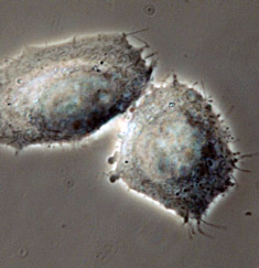
Phase contrast microscopy, first described in 1934 by Dutch physicist Frits Zernike, is a contrast-enhancing optical technique that can be utilized to produce high-contrast images of transparent specimens, such as living cells (usually in culture), microorganisms, thin tissue slices, lithographic patterns, fibers, latex dispersions, glass fragments, and subcellular particles (including nuclei and other organelles).

Presented in Figure 2 is a comparison of living cells in culture imaged in both brightfield and phase contrast illumination. The cells are human glial brain tissue grown in monolayer culture bathed with a nutrient medium containing amino acids, vitamins, mineral salts, and fetal calf serum. In brightfield illumination (Figure 2(a)), the cells appear semi-transparent with only highly refractive regions, such as the membrane, nucleus, and unattached cells (rounded or spherical), being visible. When observed using phase contrast optical accessories, the same field of view reveals significantly more structural detail (Figure 2(b)). Cellular attachments become discernable, as does much of the internal structure. In addition, the contrast range is dramatically improved.

Wave Interactions in Phase Contrast Microscopy
Phase relationships between the surround, diffracted, and particle (S, D, and P) waves in the region of the specimen at the image plane for brightfield microscopy (in the absence of phase contrast optical accessories) are presented in Figure 3. The surround and particle waves, whose relative amplitudes determine the amount of specimen contrast, are illustrated as red and green lines (respectively). The wave produced by diffraction from the specimen, which is never directly observed, is depicted as a blue wave of lower amplitude. The surround and diffracted waves recombine through interference to generate the resultant particle wave in the image plane of the microscope. The amplitude of each wave illustrated in Figure 3 represents the sum of the electric vectors of the individual component waves.

The Phase Contrast Microscope
The most important concept underlying the design of a phase contrast microscope is the segregation of surround and diffracted wavefronts emerging from the specimen, which are projected onto different locations in the objective rear focal plane (the diffraction plane at the objective rear aperture). In addition, the amplitude of the surround (undeviated) light must be reduced and the phase advanced or retarded (by a quarter wavelength) in order to maximize differences in intensity between the specimen and background in the image plane. The mechanism for generating relative phase retardation is a two-step process, with the diffracted waves being retarded in phase by a quarter wavelength at the specimen, while the surround waves are advanced (or retarded) in phase by a phase plate positioned in or very near the objective rear focal plane. Only two specialized accessories are required to convert a brightfield microscope for phase contrast observation. A specially designed annular diaphragm, which is matched in diameter and optically conjugate to an internal phase plate residing in the objective rear focal plane, is placed in the condenser front focal plane.

In order to modify the phase and amplitude of the spatially separated surround and diffracted wavefronts in phase contrast optical systems, a number of phase plate configurations have been introduced. Because the phase plate is positioned in or very near the objective rear focal plane (the diffraction plane) all light passing through the microscope must travel through this component. The portion of the phase plate upon which the condenser annulus is focused is termed the conjugate area, while the remaining regions are collectively referred to as the complementary area. The conjugate area contains the material responsible for altering the phase of the surround (undiffracted) light by either plus or minus 90-degrees with respect to that of the diffracted wavefronts. In general, the phase plate conjugate area is wider (by about 25 percent) than the region defined by the image of the condenser annulus in order to minimize the amount of surround light that spreads into the complementary area.

The phase plate configurations, wave relationships, and vector diagrams associated with the generation of positive and negative phase contrast images are presented in Figure 6. In addition, examples of specimens imaged by these techniques are also illustrated. As previously discussed, the spherical wavefront of diffracted light emerging from the specimen plane is retarded by a quarter-wavelength relative to the phase of the planar surround (or undiffracted) wavefront. In the positive phase contrast optical configuration (upper row of images in Figure 6), the surround (S) wavefront is advanced in phase by a quarter-wavelength when traversing the phase plate to produce a net phase shift of 180 degrees (one half wavelength). The advanced surround wavefront is now able to participate in destructive interference with the diffracted (D) waves at the intermediate image plane.

 
LENS Specifications and Identification
Identification of the properties of individual objectives is usually very easy because important parameters are often inscribed on the outer housing (or barrel) of the objective itself as illustrated in Figure 1. This figure depicts a typical 60x plan apochromat objective, including common engravings that contain all of the specifications necessary to determine what the objective is designed for and the conditions necessary for proper use.
 
There is a wealth of information inscribed on the barrel of each objective, which can be broken down into several categories. These include the linear magnification, numerical aperture value, optical corrections, microscope body tube length, the type of medium the objective is designed for, and other critical factors in deciding if the objective will perform as needed. A more detailed discussion of these properties is provided below and in links to other pages dealing with specific issues.
-
Manufacturer - The name of the objective manufacturer is almost always included on the objective. The objective illustrated in Figure 1 was made by a fictitious company named Nippon from Japan, but comparable objectives are manufactured by Nikon, Olympus, Zeiss, and Leica, companies who are some of the most respected manufacturers in the microscope business.
-
Linear Magnification - In the case of the apochromatic objective in Figure 1, the linear magnification is 60x, although the manufacturers produce objectives ranging in linear magnification from 0.5x to 250x with many sizes in between.
-
Optical Corrections - These are usually listed as Achro and Achromat (achromatic), as Fl, Fluar, Fluor, Neofluar, or Fluotar (fluorite) for better spherical and chromatic corrections, and as Apo (apochromatic) for the highest degree of correction for spherical and chromatic aberrations. Field curvature corrections are abbreviated Plan, Pl, EF, Achroplan, Plan Apo, or Plano. Other common abbreviations are ICS (infinity corrected system) and UIS (universal infinity system), N and NPL (normal field of view plan), Ultrafluar (fluorite objective with glass that is transparent down to 250 nanometers), and CF and CFI (chrome-free; chrome-free infinity). The objective in the illustration (Figure 1) is a plan apochromat that enjoys the highest degree of optical correction. See Table 1 for a complete list of abbreviations often found inscribed on objective barrels.
Specialized Objective Designations
| Abbreviation |
Type |
| Achro, Achromat |
Achromatic aberration correction |
| Fluor, Fl, Fluar, Neofluar, Fluotar |
Fluorite aberration correction |
| Apo |
Apochromatic aberration correction |
| Plan, Pl, Achroplan, Plano |
Flat Field optical correction |
| EF, Acroplan |
Extended Field
(field of view less than Plan) |
| N, NPL |
Normal field of view plan |
| Plan Apo |
Apochromatic and Flat Field correction |
| UPLAN |
Olympus Universal Plan (Brightfield, Darkfield, DIC, and Polarized Light) |
| LU |
Nikon Luminous Universal (Brightfield, Darkfield, DIC, and Polarized Light) |
| L, LL, LD, LWD |
Long Working Distance |
| ELWD |
Extra-Long Working Distance |
| SLWD |
Super-Long Working Distance |
| ULWD |
Ultra-Long Working Distance |
| Corr, W/Corr, CR |
Correction Collar |
| I, Iris, W/Iris |
Adjustable numerical aperture
(with iris diaphragm) |
| Oil, Oel |
Oil Immersion |
| Water, WI, Wasser |
Water Immersion |
| HI |
Homogeneous Immersion |
| Gly |
Glycerin Immersion |
| DIC, NIC |
Differential or
Nomarski Interference Contrast |
| CF, CFI |
Chrome-Free,
Chrome-Free Infinity-Corrected (Nikon) |
| ICS |
Infinity Color-Corrected System (Zeiss) |
| RMS |
Royal Microscopical Society
objective thread size |
| M25, M32 |
Metric 25-mm objective thread;
Metric 32-mm objective thread |
| Phase, PHACO, PC |
Phase Contrast |
| Ph 1, 2, 3, etc. |
Phase Condenser Annulus 1, 2, 3, etc. |
| DL, DLL, DM, BM |
Phase Contrast: Dark Low, Dark Low Low, Dark medium, Bright Medium |
| PL, PLL |
Phase Contrast: Positive Low, Positive Low Low |
| PM, PH |
Phase Contrast: Positive Medium, Positive High Contrast (Regions with higher
refractive index appear darker.) |
| NL, NM, NH |
Phase Contrast: Negative Low, Negative Medium, Negative High Contrast
(Regions with higher
refractive index appear lighter.) |
| P, Po, Pol, SF |
Strain-Free, Low Birefringence,
for Polarized Light |
| U, UV, Universal |
UV transmitting
(down to approximately 340 nm)
for UV-excited epifluorescence |
| M |
Metallographic (no coverslip) |
| NC, NCG |
No Coverslip |
| EPI |
Oblique or Epi illumination |
| TL |
Transmitted Light |
| BBD, HD, B/D |
Bright or Dark Field (Hell, Dunkel) |
| D |
Darkfield |
| H |
For use with a heating stage |
| U, UT |
For use with a universal stage |
| DI, MI, TI |
Interferometry, Noncontact,
Multiple Beam (Tolanski) | | |
 |
 |
 |
Table 1 |
|


