|
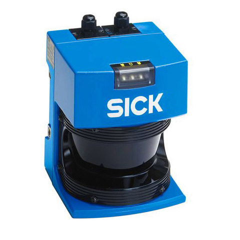
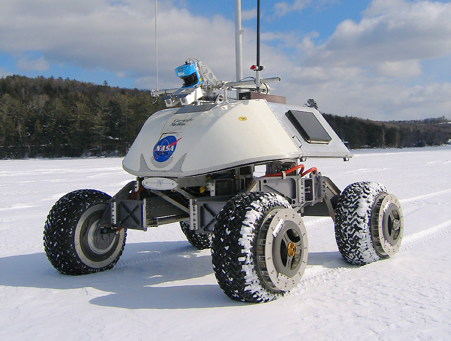
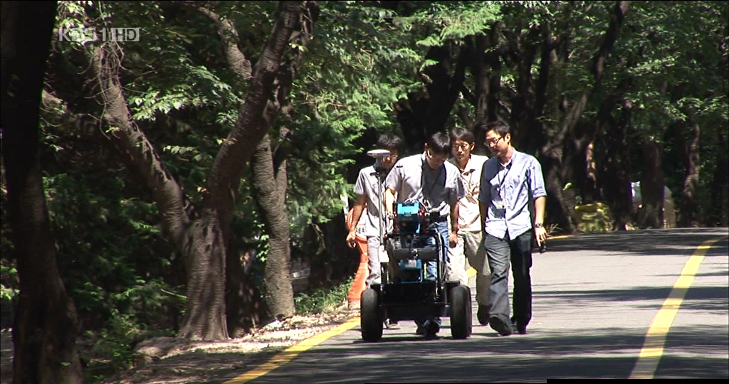
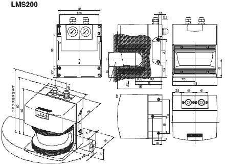
A range sensor is an important tool in mobile robotics, not only for obstacle avoidance, but also for features recognition (e.g., corners, halls, doors, human legs).
However, the first experiments should be made in simple environments with useful toolboxes as the ones available in Matlab.
|
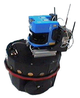 |
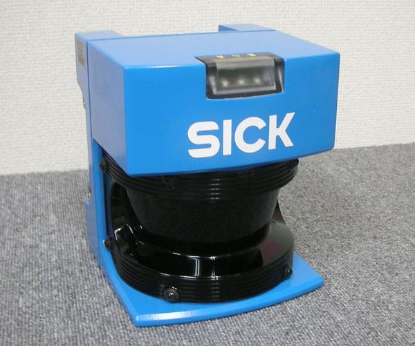
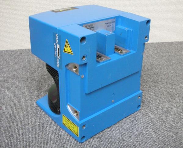
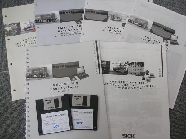
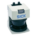
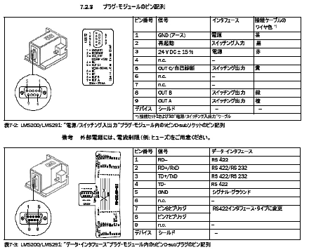
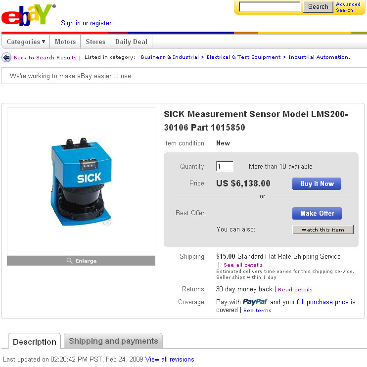
From this point forward, I identify this sensor as "Sick Laser". Since this device communicates with a computer by a serial port (RS232 and RS422), I decided to develop a simple interface in Matlab to configure the Sick Laser and to make some acquisitions. The code was tested in Matlab R13 (6.5.1).
First of all it is necessary to open a serial port to establish the communication with the Sick Laser. The serial port object returned by the function
sick_port = openPort(PORT,BAUDRATE)
must be configured according to the baudrate and other specifications (mainly the TimeOut, OutputBufferSize, OutputBufferSize for optimization purposes). For simplicity, If the user has the certainty that the serial port PORT is free and available, the previous function may be replaced by
sick_port = serial(PORT,'BaudRate',BAUDRATE)
The PORT corresponds to the serial port device (ex: 'COM1') and the BAUDRATE, the required baudrate (the possible values supported by the Sick Laser are 9600, 19200, 38400 and 500000 bps).
The next step consists on the first trial to communicate with the Laser:
testSick(sick_port)
This function tries to establish a communications with the Sick Laser at the current baudrate. If the communication fails, it tries again with a different baudrate. If the communication fails at all possible baudrates, the communication can not be established (the current serial port may be reserved/used by other software, or it must be a different serial port, or even a hardware problem, cables or the Sick Laser).
At this point, it is necessary to notice that the Sick Laser has two modes of operation: the Installation Mode and Operation Mode. The Installation Mode is defined for configurations and the Operation Mode for acquisitions. The current mode is switched by functions
chgSickInstallMode(sick_port)
and
chgSickOperationMode(sick_port)
For instance to change the current baudrate, the Sick Laser must be working in Installation Mode. By default, when the Sick Laser is switched on, it is configured to communicate at 9600 bps. The function
chgBaudRate(sick_port,NEW_BAUDRATE)
switches to the required NEW_BAUDRATE.
At Installation Mode it is possible to adopt several configurations. A wrong configuration could be solved by a hardware reset. The function
initScan(sick_port)
performs a hardware reset, similar to a power off - power on.
At this moment, the Sick Laser must be switched to Operation Mode and it is ready to make acquisitions. The function
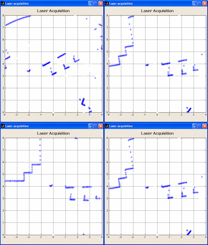
out = getScan(sick_port)
returns a vector with 361 measured values, corresponding to a scan of 180º with an increment of 0.5º.
To explain the previous functions, it is necessary to introduce the telegrams. The information or data exchanged with the Sick Laser is carried by telegrams. There are two types of telegrams,
telegrams to the Sick Laser:
| STX |
ADR |
LENG_L |
LENG_H |
CMD |
MODE |
CRC_L |
CRC_H |
and telegrams from the Sick Laser:
| STX |
LMI |
LENG_L |
LENG_H |
...body... |
CRC_L |
CRC_H |
where each cell contains two bytes (ex: STX = 02h = 0x02h = 0x02). The data is transferred in binary format and INTEL data format (word transfer takes place with lower address and the least significant byte first and then bytes of higher significance and higher address).
The telegrams finish with the CRC. For example, the following telegram requests an acquisition (CMD = 0x30 and MODE = 0x01):
| 0x02 |
0x00 |
0x03 |
0x00 |
0x30 |
0x01 |
0x71 |
0x38 |
The response starts with ACK if received correctly within 60ms or NAK if an error occurred,
If ACK is received, the next telegram is the response to the last request.
| STX |
LMI |
LENG_L |
LENG_H |
...body... |
CRC_L |
CRC_H |
The response to the previous example (an acquisition request) is
| 0x02 |
0x85 |
0xd7 |
0x02 |
...body... |
CRC_L |
CRC_H |
where the body includes the 361 sampling (722 bytes):
| CMD |
LENG_L |
LENG_H |
1st |
... |
361st |
LMI_S |
CRC_L |
CRC_H |
for example
| 0xb0 |
0x69 |
0x01 |
1st |
... |
361st |
0x00 |
CRC_L |
CRC_H |
Resuming, a telegram to the Sick Laser is compiled as follows:
msg = [STX ADR LENL(length(msg_body))
LENH(length(msg_body)) msg_body];
crc16 = crc16alg(msg);
msg = [msg LENL(crc16) LENH(crc16)];
where the message body (msg_body) contains the request (command and options) or the answers (e.g. the current acquisition values). The length of the message body is simply evaluated by
function number = LENL(number)
number = mod(number,256);
function number = LENH(number)
number = (number-mod(number,256))/256;
The CRC or CRC16 is a quick conversion from the C code (referred in the Sick Laser manual) to Matlab. This simple version works, but I believed that it could be optimized :-) Suggestions are welcome!
function crc16 = crc16alg (msg)
CRC16_GEN_POL = 32773; % 0x8005
crc16 = 0;
abData(1) = 0;
len = length(msg);
for f=1:len
abData(2) = abData(1);
abData(1) = msg(f);
if crc16 > 32768 % (crc16 & 0x8000)
crc16 = mod(crc16,32768) * 2;
% crc16 = (crc16 & 0x7fff) << 1;
crc16 = binvec2dec(xor(dec2binvec(crc16,24),
dec2binvec(CRC16_GEN_POL,24)));
else
crc16 = crc16 * 2; % crc16 <<= 1;
end;
% crc16 ^= MKSHORT(abData[0], abData[1]);
abData(2) = mod(abData(2),256) * 256;
crc16 = binvec2dec(xor(dec2binvec(crc16,24),
(dec2binvec(abData(1),24) |
dec2binvec(abData(2),24))) );
end;
Some examples of telegrams are presented. In each telegram, the message body (msg_body) is set by the command and options (if required).
For initialization, which is equivalent to a hardware reset (a power off - power on):
CMD = 0x10;
msg_body = CMD;
To testing the device:
CMD = 0x31;
msg_body = CMD;
For changing to a new BaudRate (MODE = 0x42, 0x41, 0x40 and 0x48, equivalent to 9600, 19200, 38400 and 500000 kbps)
CMD = 0x20;
MODE = 0x40;
msg_body = [CMD MODE];
As previously referred, the Sick Laser works at two different modes: Installation Mode and Operation Mode. For switching to Installation Mode it is necessary to introduce the password (in this case, the password is "SICK_LMS", equivalent to
0x53 0x49 0x43 0x4B 0x5F 0x4C 0x4D 0x53 in ASCII)
CMD = 0x20;
MODE = [0x53 0x49 0x43 0x4B 0x5F 0x4C 0x4D 0x53];
msg_body = [CMD MODE];
For switching to Operation Mode
CMD = 0x20;
MODE = 0x25;
msg_body = [CMD MODE];
Finally, for an acquisition:
CMD = 0x30;
MODE = 0x01;
msg_body = [CMD MODE];
Send and Receive Telegrams
|
The next step describes how to exchange the telegrams. This goal is accomplished by two simple functions,
function sendMsg(sick_port,msg)
fwrite(sick_port,msg,'uint8','async');
delay(sick_port,0)
and
function msg = getMsg(sick_port,len)
delay(sick_port,0);
if sick_port.BytesAvailable
msg = fread(sick_port,len,'uint8');
else
msg = [];
end
Both functions require a delay (testing the transfer status of the current serial port). This function must include the instruction "drawnow", otherwise the user can not interrupt the acquisitions (even with Ctrl+C).
function delay(sick_port,time)
while (strcmp(sick_port.TransferStatus, 'read') |
strcmp(sick_port.TransferStatus, 'write') |
strcmp(sick_port.TransferStatus, 'read&write') |
toc drawnow
end
If necessary, the following function flushes the buffer.
function flushBuffer(sick_port)
delay(sick_port,0);
if sick_port.BytesAvailable
fread(sick_port,sick_port.BytesAvailable,'uint8');
end
In practice, some of these functions have few hidden lines of code. For instance, imagine that the cable is suddenly unplugged. The acquisition was waiting for a response! Or, if the power supply fails, the Sick Laser is reseted and switches to 9600 bps again. However, the current serial port is opened at 38400 bps! In these and other situations, an interrupt event may occur (or not!). Therefore, the code should cover all the possible unexpected situations.
The interface was only tested at 9600, 19200 and 38400 bps (at 500000 bps a special serial port controller PCI or PCMCIA is required), on a Laptop Pentium M 1.4GHz - 512MB of SDRAM with Windows XP - SP1 and Matlab R13 (6.5.1). The sampling rate at 38400 bps was near to 1.8 scanning per second (a
scanning of 180º with 361 values).
|